- Member ID
- #1139
- Messages
- 3,823
- Reactions
- 9,056
- Likes
- 252
- City
- Nanticoke
- State
- PA
- Country
- United States
- Vehicle
- 2016 Challenger He’ll Cat
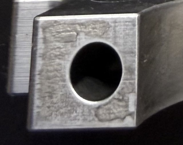
Some engine 101 diagnoses for those interested in learning.
I was asked by someone for my opinion on engine failure. These pictures tell tales.
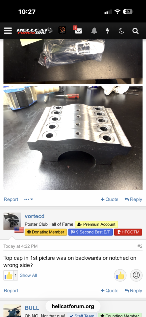
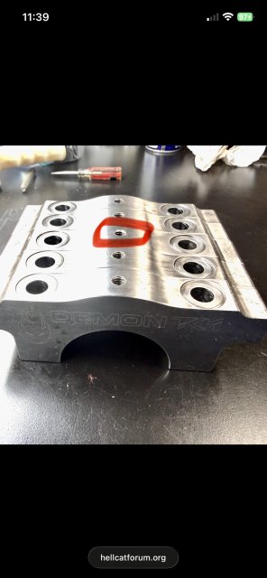
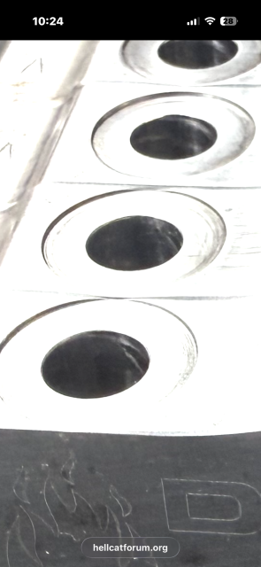
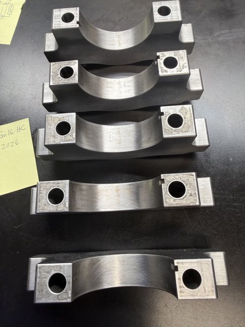
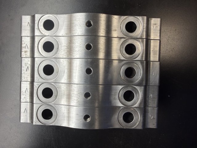
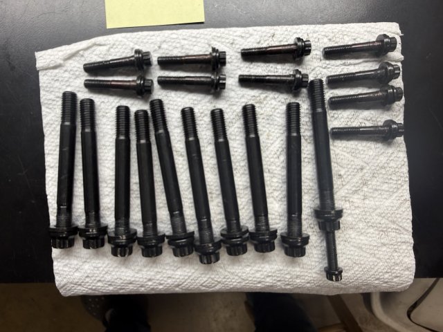
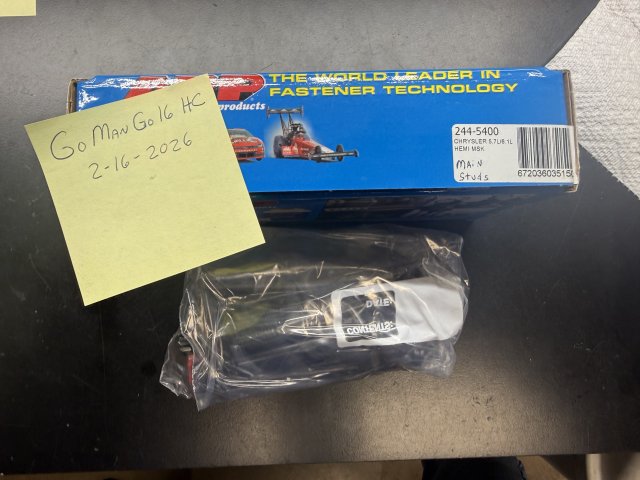
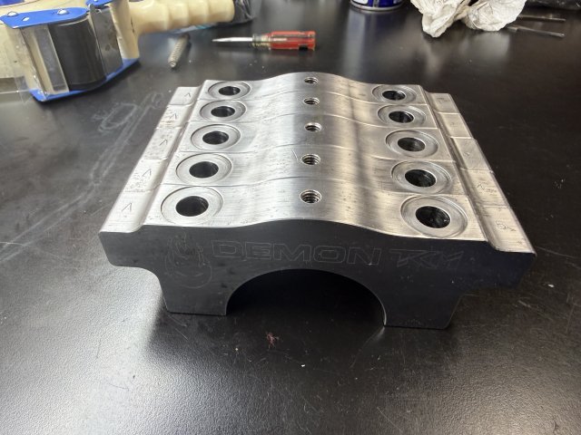
Photos are of a set of billet main caps that were fitted to strong Redeye block. All premium parts were used, Callies Compstar Crank, Boostline Rods, Wiseco Custom Pistons, ARP Studs, etc. These main caps held down by ARP main studs pictured, One would think about a bullet proof rotating assembly right? Nope!! So what happened? The tell tail is in these pictures. Anyone care to guess what went on here? Tune was right on, was making over 1500 to the wheels twin turbo. Had multiple power settings in the tune, 1000, 1300, 1500. On 1500 it went BOOM. No detonation, no nothing showing bad in the logs, all was great then BANG, disaster. What is seen here? And what needs to be better next time and why? (Aside from 4 bolt main caps on at least the center 3 caps).
I was asked by someone for my opinion on engine failure. These pictures tell tales.
Photos are of a set of billet main caps that were fitted to strong Redeye block. All premium parts were used, Callies Compstar Crank, Boostline Rods, Wiseco Custom Pistons, ARP Studs, etc. These main caps held down by ARP main studs pictured, One would think about a bullet proof rotating assembly right? Nope!! So what happened? The tell tail is in these pictures. Anyone care to guess what went on here? Tune was right on, was making over 1500 to the wheels twin turbo. Had multiple power settings in the tune, 1000, 1300, 1500. On 1500 it went BOOM. No detonation, no nothing showing bad in the logs, all was great then BANG, disaster. What is seen here? And what needs to be better next time and why? (Aside from 4 bolt main caps on at least the center 3 caps).
-
 1
1
- Show All
")